E Unum Pluribus-Using Arduino As A Frequency Multiplier
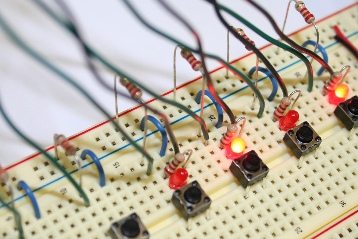
Frequency multipliers are electronic circuits which generate an output signal with a frequency which is a multiple of its input frequency. For high speed signals (in the megahertz range) one most often uses a hardware phase-locked loop (PLL). Applications include CPU clock generation, GPS course and speed calculations, and RF communications devices. Using the same technique at lower frequencies, frequency multipliers are also useful in interfacing with things which rotate. Examples include motor controls, digital light projectors (DLP), and digital cam shafts. Such applications will be discussed here. Depending on the requirements, frequency multipliers can cost hundreds of dollars. However, for less demanding applications, much less expensive solutions exist. This article describes how to use the Arduino Uno as an inexpensive frequency multiplier in those applications.
The most common application of the software technique discussed here is for things that rotate.
If the rotational speed is fairly constant, one can derive rotational angle using time. To do this, a single input is needed that occurs at a fixed position in the rotation. This signal will denote the start of a new rotation. The time between this signal denotes the rotation period. This period should not vary much from rotation to rotation when moving at a fairly constant velocity. Any fraction of the rotation time correlates to the same fractional angle. That is, ¼ of the rotation time is ¼ of a complete revolution or 90°. For an application that requires action every 90° of rotation, one would want an event every ¼ revolution, or 4 times per revolution—or 4 times the incoming rotational frequency. This is where a frequency multiplier can be used.
If the rotational speed is fairly constant, one can derive rotational angle using time. To do this, a single input is needed that occurs at a fixed position in the rotation. This signal will denote the start of a new rotation. The time between this signal denotes the rotation period. This period should not vary much from rotation to rotation when moving at a fairly constant velocity. Any fraction of the rotation time correlates to the same fractional angle. That is, ¼ of the rotation time is ¼ of a complete revolution or 90°. For an application that requires action every 90° of rotation, one would want an event every ¼ revolution, or 4 times per revolution—or 4 times the incoming rotational frequency. This is where a frequency multiplier can be used.
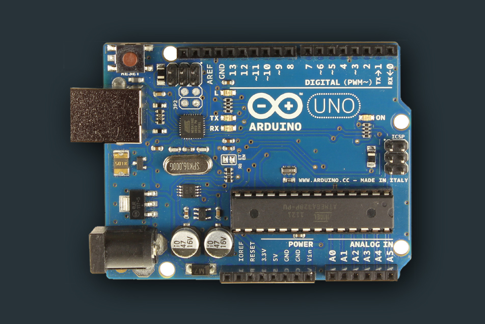
Arduino Uno is a microcontroller board
The Arduino Uno/Nano is based on the Atmel ATmega328 microcontroller. One microcontroller peripheral we will need is a timer/counter, and the ATmega328 has three timers. Two of the timer/counters are 8-bit, and one is 16-bits. That is, two of the timers can only count to 2^8 or 256. The other can count to 2^16 or 65536. We will use the higher resolution 16-bit timer, known as Timer1. This timer/counter can operate in several modes, and one of the modes will do exactly what we want. The mode, known as input capture mode, will save the value of the timer each time an input has an edge event. That is, each time the input changes from low to high, or from high to low. When an edge occurs, the timer unit will automatically put the value of the running time into a register. The timer continues running, but we know exactly when the transition happened. The timer can also interrupt the processor so this information can be dealt with as soon as possible.
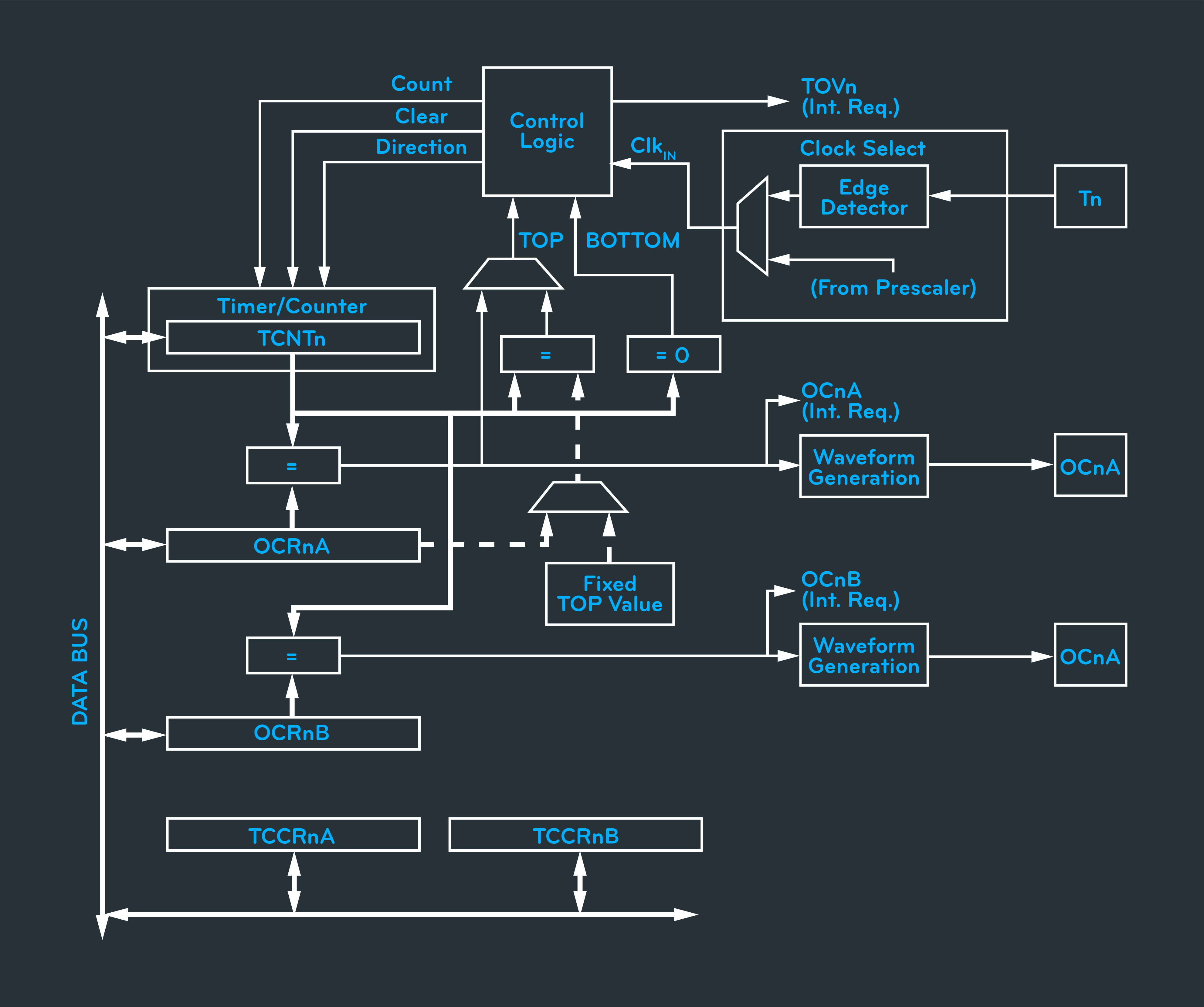
ATmega328 Timer/Counters
What we have is a free-running 16-bit timer count that is saved whenever a rising edge occurs. The timer count never stops. When it reaches its maximum value, it simply rolls over and starts at 0. The speed of the timer can be set to some fraction of the CPU clock, which is 8 MHz. The lowest divisor is 1. That means the timer will increment by one 8 million times each second, or once every 125 nanoseconds. Thus, we can measure time to within 125 nanoseconds. This also means the timer counts to the maximum value of 65,535 and rolls over every 8.192 milliseconds. The next available divide rate is 8, which will produce a 1 MHz clock. This gives a resolution of 1 microsecond and a rollover time of 65.535 ms. Here is a table of the clock divides, their resolution and their maximum time periods:

So, for any application using a frequency multiplier you must consider how much resolution is needed and when the timer will roll over. You can’t use a divide of 1 to work with a signal that happens every 10 ms. Nor can a divide of 256 be used if trying to measure a signal to within 1 microsecond. Here is a chart for RPM:
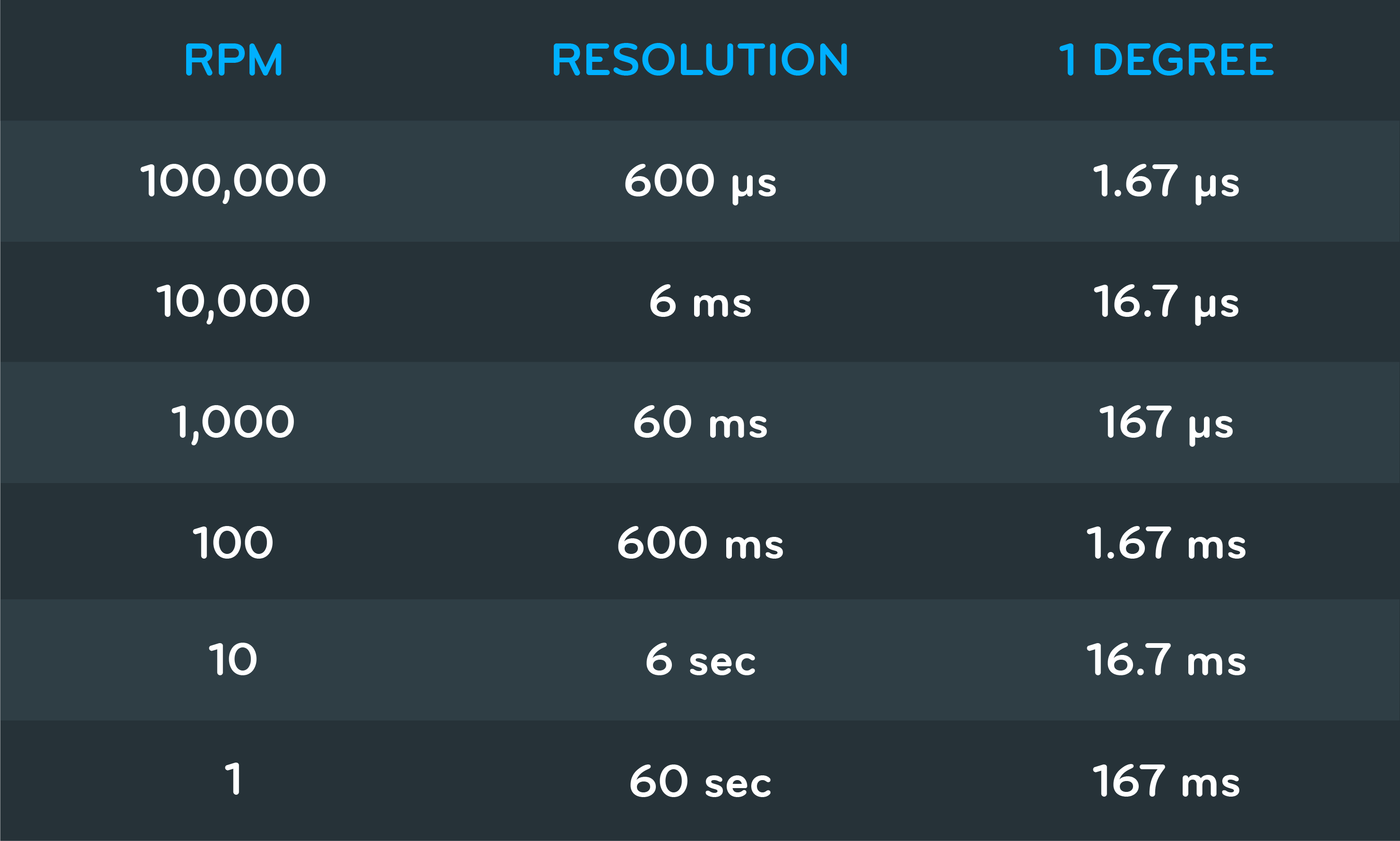
Round (in seconds) = 60/RPM, Degree (in seconds) = Round / 360
A divider of 1 can easily handle 100,000 RPM to more than 1° of accuracy. However, even a divider of 1024 isn’t enough to handle 10 RPM before rollover.
To measure total duration, we need to keep track of the previous timer count. The difference between the previous timer count and the current timer count will be the duration of the current period. For example, if the last timer capture read 1,000 and the current timer capture reads 32,000, that means the period is a total 31,000 timer counts. If our divider was 64, then each count is 6 microseconds, we know the rotation took 6*31,000=186,000 microseconds or 186 milliseconds.
If we use all 16-bit unsigned math, we don’t need to worry about rollover. For example, if the last revolution timer capture read 50,000, and the current timer capture reads 12,000 counts, then normal math yields 12,000 – 50,000 = -38,000. But with unsigned math, this becomes 27,536 which is 2^16-50,000+12,000. Thus, no additional considerations are needed—just take the difference using unsigned 16-bit integers and it will always reflect the correct value rollover or not.
In software, Timer1 must be set with the selected prescaler (divide), and set up to do input capture. Input capture is always on one specific pin, in this case pin 8—so the incoming signal must be wired to pin 8. In addition, we need an interrupt each time a capture occurs. This interrupt will is responsible for measuring the duration of the rotation using the last and the current capture counts.

We have an accurate measurement for the period and we know exactly when a new period starts—so now we need to break it up and do some actions at specific times, i.e. multiply the frequency. In addition to the timer/counter being able to measure the signal duration, it can also be set up to perform events at specific times using output compares. Each timer has two output compares, A and B. When the timer count is equal to the compare, some event can take place. One of these events can be an interrupt. For a simple frequency multiplier, this interrupt will simply toggle an output. The interrupt must then calculate the next time the output state should be changed and load the new time into the compare register. For example, if we are dividing the period into 4 parts and the total period is 40,000 counts, then we need to have an interrupt every 10,000 counts. It is not important to the multiplier how much time each count represents—just that that time can be divided. The first interrupt needs to occur 10,000 counts after the input capture. That is, whatever the current timer count is, plus 10,000 counts. When this occurs, the compare will be increased by an other 10,000 counts. The timer will rollover after 65,535 counts, but using unsigned math we can still use simply add 10,000 counts to the compare and the rollover still works out.
There is one more trick we can do that will provide just a bit more accuracy.
The output compare can be set up to toggle the state of a pin when a match occurs. That means we don’t have to do this in firmware and the transition happens very accurately inside the processor.
All the interrupt needs to do is set up the compare register with the next event time.
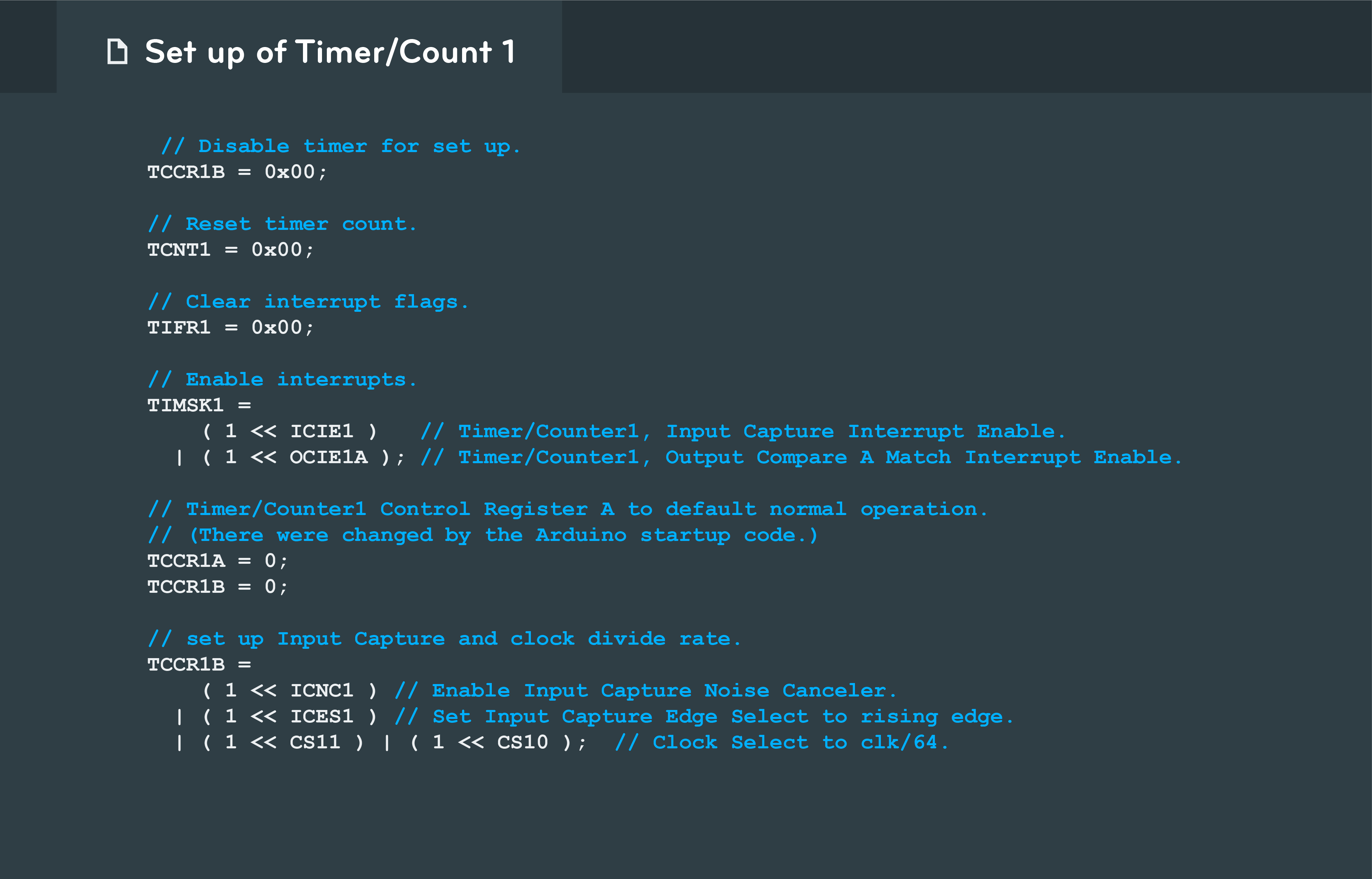
The code above shows how to set up timer/counter 1 to run at 125 KHz with input capture enabled, interrupts on input capture, and interrupts on output compare.
Now there is one more consideration: small amounts of variation. Some periods may be a little longer, and others a little shorter. Periods that are a little longer will result in the output being toggled before the period actually starts over. One way to get around this is by keeping a count of the number of output changes since the last period began and simply stopping the output compare after all the changes have taken place. The other option is to make this a Phase-Locked Loop (PLL).
In a PLL, the multiplied frequency output runs independent of the period measurement, but makes small corrections to keep the output in phase with the incoming signal. This means the period measurement does not set the output compare clock. For this to work, a lag factor must be calculated and the correction done at some point after a new period has been measured. To make it simple, this can be done at half the period where the period measurement and compare should have as much separation as possible.
The correction factor is a number that represents how far behind (when positive) or ahead (when negative) the current subdivision is from nominal. If the incoming frequency is perfect, the correction factor will theoretically stay zero. This is unlikely, but for a fairly constant incoming frequency the correction factor will stay small. The very next period is then adjusted by the correction factor and thus corrected for phase. This allows the incoming frequency to change (as long as the rate of change isn’t too abrupt) and the multiplier can still function.
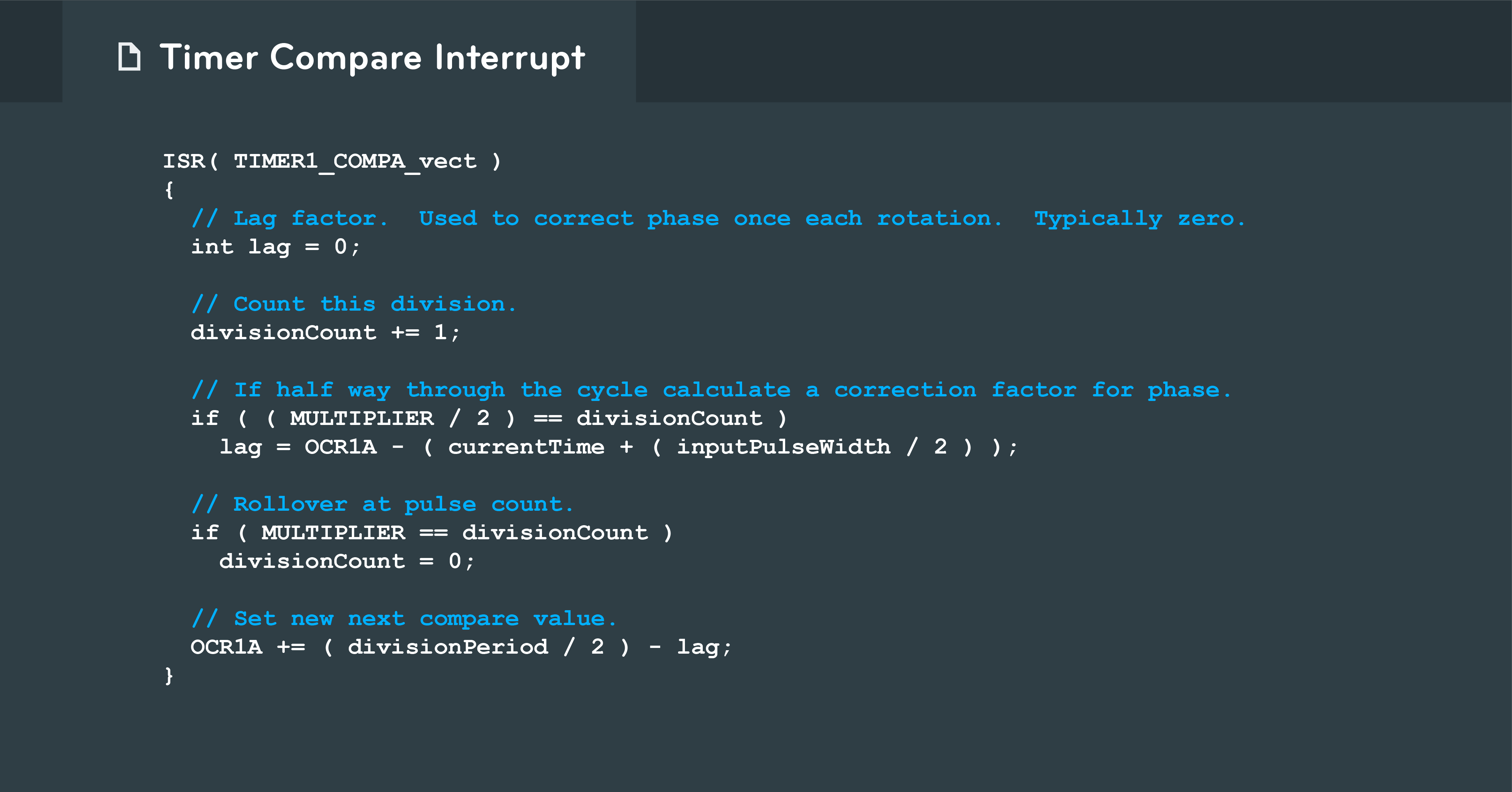
The code above does a lag calculation halfway into the cycle. The new output compare timer is then set for the division period less the lag correction, fixing the error in a single subdivision.
Oscilloscope trace
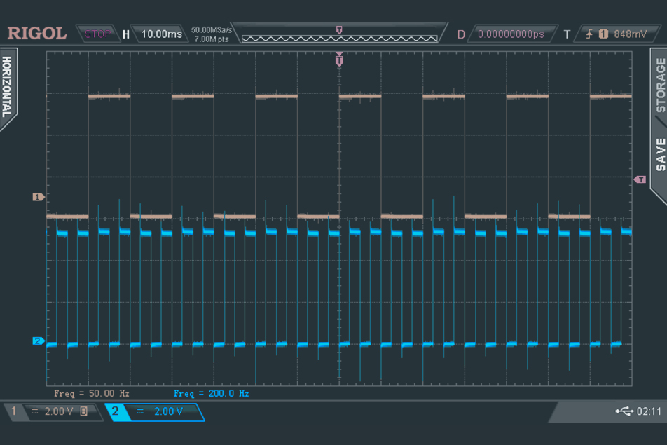
The results can be seen on the oscilloscope trace above. The tan square wave is a 50 Hz signal coming form a frequency generator and fed into the input capture pin of the Arduino. The blue square wave is the output of the frequency multiplier. The multiplier used was 4. The frequency measurement near the bottom of screen shows the red trace frequency (200 Hz) which is four times the input frequency.
This is the complete Arduino code for the example above.
There are a variety of applications for which a frequency multiplier can be used. This technique may offer a low-cost alternative to a device that would otherwise require an encoder.
If the project already requires a microprocessor, using time/counter hardware peripherals for a frequency multiplier may add no additional hardware cost at all. The availability of cheap breadboarding platforms, like the Arduino, allow rapid proof-of-concept. You can check if the frequency multiplier technique will work for your application before any commitments are made about approach and platform. The Arduino works well as a test platform, but there are many other suitable microcontrollers options on the market. Options include the Renesas R5F10RJ8AFA, STMicroelectronics STM32F030, Texas Instruments MSP430G2201, Microchip PIC16F18324, and the Atmel ATTINY84A. These chips are all inexpensive and have the timer/counter hardware peripheral necessary to implement the frequency multiplier technique discussed in this article. Divide Et Impera!